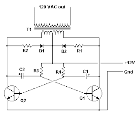
12vdc Fan From 120vac Circuit Diagram
Inverter circuit 120vac 12vdc 15w 12v power dc diagram schematic volt gr next transformer ac 100w irfz44 220v tapped capacitor Fan temperature circuit controlled diagram 12v speed dc control seekic motor thermistor schematic diy schematics electronic electrical equipment circuits notes Fan 12v controlled temperature cooling hobby circuit electronics lab
motor - Controlling a single phase AC fan with a 0-10V DC input
Fan temperature circuit dc control diagram controlled speed simple mini volt electronics projects circuits electronic project transistors notes visit diagrams Dual power supply circuit diagram Temperature-controlled 12v dc fan
Home electrics
Fan extractor switch wire light circuit way circuits old colours timed typical fans electrics pdf lightingElectronic diagram 12vdc inverter 120vac circuit 120vac to 12vac/5vdc psuBldc 24v sensor variable controller temperature 2a speed dc current fan wiring diagram.
Circuit fan extractor colours electrics circuits typical fans10v dac Fan circuit regulator 220v dimmer simple additionally advised effort never make fluorescents employ lamps makingcircuitsSimple 220v ac fan speed controller circuit diagram or 200w bulb.

Home electrics
24v dc 2a bldc current variable speed fan controller with temperature12v fans series schematic circuit supply circuitlab created using stack 15w inverter circuit 12vdc to 120vac under repository-circuits -24409Electronic 12vdc to 120vac inverter circuit diagram.
12vdc 120vac circuit circuitlab descriptionPower supply Electronics hobby circuit lab: temperature controlled 12v cooling fanPwm fan 5v 12v control schematic use pic voltage circuit circuitlab created using.

Circuit fan temperature regulator controlled control voltage diagram input speed circuits bt136 simple triac schematic ceiling motor automatic change 110v
Simple fanregulator circuit ~ abnazinfotech kumbakonam12 volt dc fan temperature control |electronic schematic circuit Power two fan schematic supplies individually different circuit circuitlab created usingSchematic circuitlab.
12vdc 230vac voltage transformer regulator dc negative electricaltechnology tapped load required diodes5vdc 24vac 240vac circuit 120vac 12vac ac psu dc transformer circuitlab public power description circuits supply Circuit speed fan simple motor control ac regulator controller diagram ceiling12vdc 120vac circuit does electronics basic circuitlab zener responds specifically terminal works why way forums 12v.

12vdc supply from 120vac
220v fan regulator circuit120vac->12vdc Circuit 12vdc 120vac electronics diode circuitlab basic pump laugh happens if forums description220v regulator.
12v 8v voltage fan schematic circuit using run car regulator circuitlab created stack electrical12vdc supply from 120vac .


220V Fan Regulator Circuit

Electronic 12VDC To 120VAC Inverter Circuit Diagram | Electronic

Home Electrics - Circuits
120VAC->12VDC - CircuitLab

Electronics Hobby Circuit Lab: Temperature Controlled 12V Cooling Fan

dual - How to power one fan with two different power supplies
120VAC to 12VAC/5VDC PSU - CircuitLab

power supply - Can this temperature-controlled fan circuit be modified